ФНЧ до 145 МГц
| Уголок радиоконструктора |
High Power Lowpass Filter for 145 MHz
Here I want to describe how to build a low-pass filter for 145 MHz as required after power amplifiers to prevent harmonics to be emitted by the antenna.
I've used the freeware tool "RFSim99" to design the following filter:
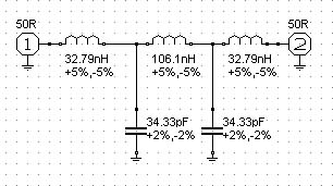
It has a cutoff frequency of about 150 MHz.
Because the filter should handle 500 Watts of continuous power, I decided to build it by etching the capacitors on a PTFE PCB, thats much cheaper than ordering several capacitors (which are usable for VHF; many aren't!): By cutting the copper areas you can easily adjust the capacitance.
The inductors are made of 2mm silver-coated copper wire and calculated with the "Mini Ringkern Rechner" where you can enter the inductance and coil diameter and the program tells you how many windings and which spacing you need.
And so the filter looks like:
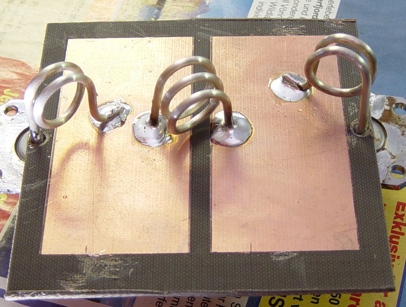
You can see the input and output connectors mounted for measuring; later in the PA there will be a piece of Aircell 7 soldered to the filter directly.
And here the measurements of this filter (hope the pictures are readable but my GPIB interface isn't available at the moment ...):
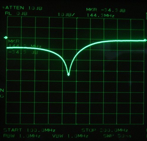
Return loss (optimized for the 144,3 MHz SSB call frequency):
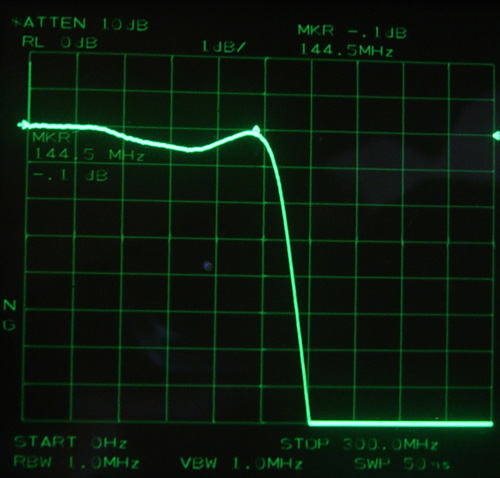
Insertion loss:
Attenuation at 1st harmonic (288 MHz):
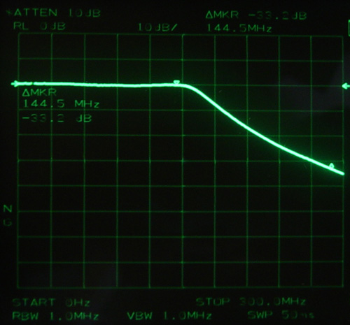
You can see the filter has only about 0.1 dB insertion loss at its design frequency !!
So only about 10 Watts of my 500 Watts will be lost ! Thats really great! At 400 Watts it gets only a little bit warm after transmitting for several minutes
In an earlier design I've tried to build the filter on a FR4 epoxy PCB but this got really warm after one minute with 100 Watts, but it worked, too. It's a pity I didn't save the screenshots of the measurements of this filter to compare them in a table here ...