Устройство выходного дня
| Уголок радиоконструктора |
От редакции Радона. Мало кто из авторов публикаций раскрывает все секреты своих
конструкций. В данном случае, можно не только собрать неплохой прибор для
измерения мощности и КСВ в цифровом виде, но и научиться тому как это
делается на практике. Ведь автор не только дал прошивку, но и все исходные
коды, программу для прошивки. Если учесть, что плата Ардуино-нано на
Алиэкспрессе стоит около 60 грн плюс дисплей примерно столько же,
то за символическую плату вы становитесь обладателем неплохого изделия.
Еще и свой позывной введете на табло. Итак, в путь!.. Обратите внимание,
что не каждый браузер корректно отображает страницу. Хром брыкается,
а к примеру, Файрфокс открывает нормально. Чтобы не было лишних проблем, советуем ререйти
на ссылку внизу статьи.
RF Power & SWR meter with Average and Peak
Overall this is an accurate meter, fantastic for a meter under $20, good performance across all
of the HF bands using fairly common parts and simple construction techniques.
Meter and RF Sensor Wiring Diagram
The Stockton bridge circuit is selected uses a fixed 50 ohm reference loads. This is a very simple circuit
just a forward and reverse set: current transformer, a diode, resistor, filter capacitor and connectors. RF
is passed in one connector and out of the other to some unknown antenna impedance. The transformers
feeds a fraction of the RF current passing to the respective forward or reverse resistor. The sampling
fractions, usually is proportional to the square of the turns. Example: using 10:1 turns would see 1% of
the RF current at the reference resistor. Current ratio is proportional to the ratio squared. The little Arduino
Nano uses the forward and reverse DC voltages to calculate RF power and Voltage Standing Wave Ratio.
See "Decide on these options before you build" for resistor information.
The prototyping breadboard is a good way to test everything while
the connections are easy to get to for trouble shooting prior to installation inn enclosure.
How does it work?
Working with one Watt output transmitter and didn’t have anything suitable for measuring under five watts
and nothing with a meter that would wiggle a one watt.. At first I just measured the RF at the dummy load
with an oscilloscope. I new one Watt of RF peak to peak voltage on a 50 Ohm load is about 20 Volts.
Even at 10 Watts the voltage is only 63 Volts. So for a while I could adjust my bias levels, peak my output
and check for clipping. This was fine for QRP, but it was tying up my scope and I only needed the peak
voltage of the RF envelope so I setup a rectifier and a digital volt meter to get the same answer. I setup
a dummy load with a coax tee adaptor, a short test lead to PCB holding an RF diode, filter and banana
plugs to a digital volt meter, shown here.
Temporary Bench Test RF Power Monitor
Voltage - Wattage Spreadsheet
The DVM method worked but, I was spending too much time calculating watt values. The next problem
I faced was a power increased the peak reverse voltage (45 V) of a 1N34 diode is reached at just five
watts. I could switch to a 1N270 diode or go back to the oscilloscope for higher voltages, but I wanted
a Wattmeter for my bench work. It didn’t need 1% accuracy, 5% would be good enough. I found some
readymade QRP meters the power range, but I never have liked adjusting for forward power and
switching to read SWR. I wasn’t keen on buying one of those BIG face meters and the digital ones
cost even more, nothing seemed to fit my purpose and budget. I continued on for some time using
a spreadsheet with the voltages (Vpp, Vp, Vrms) and wattage something like the one shown.
It only took me a few days to get tired of having to change screens on a laptop just for a wattage
spreadsheet to grow weary. I had a peak voltage value and wanted a wattage answer, so decided
to temporally reprogram a homebrew Arduino based keyer sitting on my bench. Just attached clip
leads to the pins. Then a few lines of software and resistive voltage divider (to protect the A/D inputs)
for the diode voltage. Some of you are ready to stop reading at the idea of software, but you can multiple
and divide using a calculator or a spreadsheet you can work with the Arduino. The Arduino
microprocessors are not much smarter than a calculator, they just don’t mind do the same
thing over and over again. There you have it, inspiration out of necessity. It was not pretty
but it was a wattmeter for my bench work was born.
The sampling circiut I built is based on a Stockton Bridge. UHF Coaxial (SO-239) chassis
connectors are mounted on opposite faces of a metal box. The RF sensor is a Stockton
bridge directional coupler, it turns the forward and reflected power into voltage levels that
can be translated into power levels. The current through the line is sampled with the aid of
toroid RF transformer windings and applied to termination resistors, The power levels on
the termination resistors are proportional to the input power divided by the square of the
toroid turns ratio. Diode detectors are connected to the termination resistors to convert the
bridge outputs to dc levels, see the Stockton Bridge Circuit diagram shown below ;
Stockton Bridge Circuit diagram
Understanding how the Stockton Bridge works and why antennas have forward RF power
and reverse RF power (reflected back) is the stuff college text books are better suited.
You will find dozens of homebrew SWR meters based on Stockton’s design by searching
on Stockton Bridge circuit or G4ZNQ. I have found two extremely good mentors on YouTube
I toughly recommend; David Casler KE0OG has a great video on understanding SWR ( YouTube KE0OG )
and Alan Wolke W2AEW has a detailed demonstration on the Stockton Bridge ( YouTube W2AEW ).
To know more about HAM radio I recommend you check out all of Dave Casler’s videos for hands
on information and Alan Wolke’s videos for details how radio related equipment works.
The bridge is constructed using Single-sided PC board (glass-epoxy material recommended) as a
double-sided board would introduce capacitance and this might influence the bridge. I made my
own board one inch square to mount the resistors and diodes and connection for the windings.
The capacitors are at the 3.5 mm connector terminal pins to keep RF inside the box.
Bridge Circuit on Circuit Board
The termination resistors provide the bridge forward and reverse power outputs to dc levels,
Voltage Peak (Vpeak) level to be exact. The Arduino analog to digital converter compare the
Vpeak then computers do all the math. It is important to understand you start with peak and
convert to RMS to find the actual power. The Arduino Nano uses a 5V default reference for the
digital converter. The resistor voltage does not include the diode voltage drops of about 0.3 V
for a 1N270 and the drop is corrected mathematically in the software program. Resistor Voltage
Peak = Arduino Steps X 5 Volts divided by the A/D value for 5V then add the diode voltage drop.
I considered multiple power ranges and decided not build in a power range selector switch as I
find it is only a matter of time before, OOPS wrong range! Buy a new meter! I try not to repeat
my costly mistakes. The calculations shown below apply to a circuit using transformers with a
13:1 turn ratio. Typically 10:1 is used for low power and more turns at higher power in the bridge
circuit. I picked 13:1 as it was easy to wind on a small toroid and a middle range, low enough to
measure 1 W and only consumes 0.5% of my forward power.
Resistor Voltage RMS = Resistor Voltage Peak X 0.707 X 13 (turns ratio)
Amps = Resistor Voltage RMS / 50 Ohm Termination Resistor
Amps = [ Steps X 5 ) / 1023 ) + 0.30 ] X [ 13 X 0.707 / 50 ]
Amps = ( ( (Steps X 5) / 1023 ) + 0.30 ) * 0.18382
Amps = Steps X 0.000898435972629521 + 0.055146
Power = Resistance X Current Squared
Power = 50 Ohm X Amps X Amps
Use the forward and reverse power to determine VSWR
p = SQRT ( Power Reverse / Power Forward )
VSWR = ( 1 + p ) / ( 1 – p )
Select these components based on RF power range
The Inline Power and VSWR meter is a valuable tool for the antenna builder and transmitter testing.
I started this project as a bench meter to use when I was building a transmitter drive input. The idea
to build an inline power meter came out of need rather than inspiration. The design is valid for high
power or down to QRP levels. Read on for the information to make your own forward and reverse
power meter for any power level you need.
Circuit Description
Meter Prototype operating on Battery
Stockton Bridge
Getting from Voltage to Power
Decide on these options before you build


Toroid
You can use 43 or 61 Material at HF without problems. The size is not critical as the power
levels in the toroid are tiny. I used OD 0.6 Inch, ID 0.3 Inch which I found are just enough for
turns to wind and leave room for the feedthrough.
The windings are made from two 18-inch lengths of #26 AWG wire (#24-#30) with
insulation rated well above range: 25 W ~ 100Vpp, 100W ~ 200 Vpp, 1000W ~ 632 Vpp.
Diodes
Diode circuits have a diode forward voltage dropped across a current-conducting diode that
changes with a small amount of current going through it and levels off. Most simply say the
voltage drop across a conducting, semiconductor diode remains constant at 0.7 volts for silicon
and 0.3 volts for germanium. The circuit needs to use a 1N270 for low power accuracy. Many
diode based meters require more than five or ten watts at a minimum for operation to address
this drop. This meter corrects for the voltage changes with a software correction for drop vs. current at low power.
Testing 40M, 30M, 20M, 17M, 21M for 1 to 25 W gave accurate results within +/- 0.5 W. At higher
frequencies testing for 12M and 10M was less accurate with + 0 to - 1.5 W results.
Errors are a few tenths blow 3 W based on my tests. You must use identical
germanium diodes for accurate power and VSWR readings.
The resistors used in this meter must be carbon film. Carbon film are stable at HF and low
power relative to their values. Two 100 Ohm 1% resistors are used in parallel to get an accurate
50 Ohm reference. Wattage depends on power range, (examples; 2W for 150W, ¼ for 25W).
The series 10K resistors are terminations to protect the A/D inputs from overvoltage damage
and appropriate for 150W. The parallel 10K resistors are terminations to protect from damage
due to stray voltages.
The inline bridge enclosure provides protection from high voltages. I recommend a metal
project box over plastic as it also provides RF shielding. The RF feed through can be a
single conductor which is fine at HF. At 2M and up a few inch length of RG-58 coaxial
cable but it is important the shield braid is grounded at only one end. Another method is
to remove the outer insulation and shielding braid from the center one inch that passes
through the toroid. The coax braid serves as a Faraday shield to discourage unintended
capacitive coupling.
Inline Bridge Circuit in Enclosure
The ground for the PC-board and SO-239 connectors are soldered to one common copper buss to
ensure conductivity. Past projects have had intermittent connections due to zinc, chrome, copper, and
aluminum interactions over time that are not always overcome by star washers. I used a 4.5 X 2.5 X 2
inch Die Cast Aluminum Box with cover as it was the smallest I had that would permit inside mounting
of the SO-239 connectors. Most cast or bend aluminum box will provide shielding to keep you RFI under control.
LCD 5X7 Matrix Displays
The Liquid Crystal Display shown is a blue and red 4 Line 20 Character LCD Module with a
backlight and IC2 serial link. If you are an Arduino beginner, I have listed the specifics below.
If you have used other LCD displays editing the code for your display should be simple.
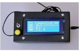
When you have finished transmitting the display will continue to display the “Transmitting” data with
zero watts for a small delay before displaying the “Average/Peak” data. The code values are loaded
with typical SSB values (averaging periods & delays) to allow for the dynamic modulation. You find
comments in the code that should help you in customizing the meter to taste.
Average and Peak Display
Resistors
Enclosure for Stockton Bridge


Arduino
Use the Arduino Nano based on the ATmega328 (Arduino Nano 3.xx). If you have used other
Arduino processors editing the code should not be problem. You must use a 5 volt reference
or modify the code/hardware to match your design.
I used a 5 X 3 X 2 Inch ABS plastic enclosure just big enough for the display and switches
on the face. You should consider more space if you are using a battery for power. I mounted
a female 2.5 mm power connector on the rear panel for connection to the remote power supply.
Series Regulator Power Supply
I use a simple series regulator for my 8V shown here and any wall plug power supply from
my junk box. The LM7808 is a three terminal positive regulator. I have found a heatsink is
not required with the TO-220 package.
Power Supply Choices
The power supply needs to supply 8 to 12 V @ 60-80 mA for the processor and back-lighting
of the LCD display. The Nano has a built-in regulated 5 V output for the display. Since the
power requirements are small, less is better in this case as the higher voltage requires more
heat to be dissipated in the Nano board. Battery operation will require a AA battery 6 pack
for a reasonable operating time like you would expect from a portable radio. I tried a 9V
battery but it will only work for 20 minutes.
Quantity
Item Description and Comments
1
1
2
2
72
4
2
2
1
1
2
1
1
2
Misc
Arduino NANO ATmega 328 Rev 3.xx
LCD Display 20X4 Serial IC2 See text discussion
Toroid #61 Material OD 0.6 Inch, ID 0.3 Inch, See text
Diode 1N270 RF germanium diode with small voltage drop See text
Inches #26 AWG Dielectric Windings depends on max watts 300 V or see text
Reference Resistor 100 Ohm 1% Carbon Film See text
Capacitor 0.01 uF Ceramic 50V
A/D Resistor 10K 5% Carbon Film ¼ W Termination not critical value See text
Power Supply 8 to 12 VDC Battery vs. Power Supply, See text discussion
Bridge Enclosure Metal Inside ~ 2 X 2 X 4 Inches, See text discussion
RF Connector SO-239 Chassis Mount
Display Enclosure Plastic Inside ~ 2 X 4 X 6 Inches, See text discussion
Signal Cable Stereo 3.5 mm Male to Male Audio cable, length 3 to 25 Ft
Signal Jack Stereo 3.5 mm Female Chassis Mount
Hookup Wire #24 to #30 AWG Color coded wire helps prevent mistakes
Warning on "See Text" items; these component values are based on maximum RF power
Enclosure for Display & Arduino
Parts List
Software
// THIS SOFTWARE IS BEING PROVIDED "AS IS", WITHOUT ANY EXPRESS OR IMPLIED WARRANTY TO USE IN YOUR AMATEUR RADIO EXPERIMENTS.
// ALL LICINCED AMATEUR RADIO OPERATORS ARE GIVEN PERMISSION TO USE, COPY AND MODIFY THIS SOFTWARE.
//////////////////////////////////////////////////////////////////////////////////////////////////////////////////////////////
//******* CHECK YOUR DISPLAY & LIBRARIES ***************
// Arduino 1.6.3 IDE (not tested on earlier IDE)
// I2C library (for LCD-I2C-GY-IIC-LCD)
// Check the Display IC2 address, this code uses 0x26
//////////////////////////////////////////////////////////////////////////////////////////////////////////////////////////////
#include <Wire.h> // #include <Wire.h> default to Wiring for Uno; SCL = A5, SDA = A4, VCC = 5V+, GND = GND
#include <LiquidCrystal_I2C.h> // The Arduino I2C is hard coded SDA = pin A4) & SCL = pin A5
LiquidCrystal_I2C lcd(0x26, 20, 4); // serial 20 X 4 LCD Display // Address A2 A1 A0 // 0x26 Hi Hi Lo
// Pinouts for NANO I/O // Analog VDC signals from Stockton VSWR Bridge Circiut
#define Vfwdpin_Anlg 6 // Forward Voltage Vfwd VDC A6
#define Vrevpin_Anlg 7 // Reverse Voltage Vrev VDC A7
///////////////////////////////////////////////////////
// Varibles
float Vfwd;
float Vrev;
float last_Vfwd;
float last_Vrev;
float Afwd;
float Arev;
float Pfwd;
float MaxFwd;
float AvrFwd;
float Prev;
float MaxRev;
float AvrRev;
float SWR;
float MaxSwr;
float AvrSwr;
int RFoff;
void setup()
{
lcd.init(); // this clears display for new data
lcd.backlight(); // Turn on the blacklight
lcd.clear(); // clear all
lcd.setCursor (0, 0); // go to Column, Row
lcd.print("CallSign PWR/SWR MTR"); // displays text
lcd.setCursor (0, 1); // go to Column, Row
lcd.print(" 30W Max Operating "); // displays text
lcd.setCursor (0, 2); // go to Column, Row
lcd.print("--------Ready-------"); // displays text
lcd.print("my example text here"); // displays text
lcd.setCursor (0, 3); // go to Column, Row
lcd.print("more example text "); // displays text
delay(8000); // delay 8 second
}
void loop()
{ // start of main loop // start of main loop // start of main loop // start of main loop // start of main loop
// reads inputs before actions can be taken
Vfwd = analogRead(Vfwdpin_Anlg); // read forward voltage from RF remote directional detector
Vfwd = constrain(Vfwd, 1, 1023); // Vfwd values must be greater than zero to prevent divide by zero in SWR Calc
Vrev = analogRead(Vrevpin_Anlg); // read forward voltage from RF remote directional detector
/////////////////////////////////////////////////////////////////////////////////////////////
// RF Forward / Reverse Power and VSWR Calculations
/////////////////////////////////////////////////////////////////////////////////////////////
/*
Step 1 = Convert Arduino A/D steps to current
Arduino Voltage = Steps X 5 Volts / 1023
Add Arduino V corrections for diode drop of 0.3 V
Arduino Voltage = Arduino Voltage + 0.30
Arduino V corrections for Vpeak to Vrms is factor of 0.707
Tx Line V = Arduino V X 0.707 X 13 turns ratio
Amps = Tx Line V / 50 Ohm Termination Resistor
Amps = [ Steps X 5 ) / 1023 ) + 0.30 ] X [ 13 X 0.707 / 50 ] = ( ( (Steps X 5) / 1023 ) + 0.30 ) * 0.18382
Step 2 = Convert Line current to power
Power = 50 Ohm Line X current squared
Power = 50 X Amps X Amps
Step 3 = Convert forward and reverse power to VSWR
VSWR = (1+SQRT(Prev/Pfwd)) / (1-SQRT(Prev/Pfwd))
*/
/////////////////////////////////////////////////////////////////////////////////////////////
float Vdiode = ( Vfwd / 1000 ); // gradual diode drop
// Gradual diode drop factor was tested for 40M, 30M, 20M, 17M, 21M
// Fowards Watts 0 to 25 W valid +/- 0.5 W // 12M and 10M valid + 0 to - 1.5 W
Vdiode = constrain(Vdiode, 0, 0.3); // limit drop to 0.3 V
Afwd = ( (Vfwd * 5) / 1023 ) + Vdiode; // split up calculation
Afwd = Afwd * 0.18382; // split up calculation
Pfwd = 50 * Afwd * Afwd;
Vdiode = ( Vrev / 1000 ); // gradual diode drop
Vdiode = constrain(Vdiode, 0, 0.3); // limit drop to 0.3 V
Arev = ( (Vrev * 5) / 1023 ) + Vdiode; // split up calculation
Arev = Arev * 0.18382; // split up calculation
Prev = 50 * Arev * Arev;
float fp = sqrt ( Prev / Pfwd );
SWR = ( 1 + fp ) / ( 1 - fp );
SWR = constrain(SWR, 1, 99.9); // some more than 100
if ( Pfwd > 0.2 ) // peak sample timer and no RF time out timer
{
if ( RFoff > 10000 ) // average and peak timer see text (10000 long for SSB, 2000 short for QSK)
{
lcd.init(); // this extra init clears and cleans up trash when on battery operation
lcd.clear(); // clear all
MaxFwd = 0; // clears past peaks and averages
AvrFwd = 0;
MaxRev = 0;
AvrRev = 0;
MaxSwr = 1;
AvrSwr = 1;
}
RFoff = 1000;
}
else
{
RFoff = RFoff + 1; // Countdown timer
}
if ((( Vfwd - last_Vfwd ) > 3) || (( Vfwd - last_Vfwd ) < -3) || (( Vrev - last_Vrev ) > 3) || (( Vrev - last_Vrev ) < -3) ) // previous reads are checked to reduce display flicker // +/- 3 to filter A/D noise
{
//////////// Peak Hold ///////////
if ( Pfwd > MaxFwd )
{
MaxFwd = Pfwd;
}
if ( Prev > MaxRev )
{
MaxRev = Prev;
}
if ( SWR > MaxSwr )
{
MaxSwr = SWR;
}
////////////////////////////////// average value integrator Select % values to add up to 100% // 10 / 90 is fast, 5 / 95 is medium, 2 / 98 is slow
AvrFwd = ( AvrFwd * 0.95 ) + ( Pfwd * 0.05 ); // average value integrator
AvrRev = ( AvrRev * 0.95 ) + ( Prev * 0.05 ); // average value integrator
AvrSwr = ( AvrSwr * 0.95 ) + ( SWR * 0.05 ); // average value integrator
////////////////////////////////
lcd.setCursor (0, 0); // go to Column, Row
lcd.print("=== Transmitting ===");
lcd.setCursor (0,1);
lcd.print("FWD ");
lcd.setCursor (5,1); // go to Column, Row
lcd.print(Pfwd, 1); // displays forward power as xx.x value // ",1" means one decimal place
lcd.print(" "); // to clear trailing digits
// FWD bargraph
lcd.setCursor (10,1); // go to Column, Row
lcd.print(" "); // to clear last bar
lcd.setCursor (10,1); // go to Column, Row
float bar = 12 - ( Pfwd / 2 );
bar = constrain(bar, 0, 10); // limit max bar
for (bar; bar < 11; bar = bar + 1)
{ lcd.print(">"); } // bargraph
// end bargraph
lcd.setCursor (0,2); // go to Column, Row
lcd.print("REV "); // displays menu selected // Clearing not required always 16 Char
lcd.setCursor (5,2); // go to Column, Row
lcd.print(Prev, 1); // displays forward power as xx.x value // ",1" means one decimal place
lcd.print(" "); // to clear trailing digits
// REV bargraph
lcd.setCursor (10,2); // go to Column, Row
lcd.print(" "); // to clear last bar
lcd.setCursor (10,2); // go to Column, Row
bar = 12 - Prev;
bar = constrain(bar, 0, 10); // limit max bar
for (bar; bar < 11; bar = bar + 1)
{ lcd.print("<"); } // bargraph
// end bargraph
lcd.setCursor (0,3); // go to Column, Row
lcd.print("SWR "); // displays menu selected // Clearing not required always 16 Char
lcd.setCursor (5,3); // go to Column, Row
lcd.print(SWR, 1); // displays forward power as xx.x value // ",1" means one decimal place
lcd.print(" "); // to clear trailing digits
// SWR bargraph
lcd.setCursor (10,3); // go to Column, Row
lcd.print(" "); // to clear last bar
lcd.setCursor (10,3); // go to Column, Row
bar = 12 - SWR;
bar = constrain(bar, 0, 10); // limit max bar
for (bar; bar < 11; bar = bar + 1)
{ lcd.print("#"); } // bargraph
// end bargraph
last_Vfwd = Vfwd;
last_Vrev = Vrev;
}
/////////////////////////////////////////////////////////////////////////////////////////////
if ( RFoff > 10000 ) // no RF time out
{
delay (200); // delay
lcd.setCursor (0, 0); // go to Column, Row
lcd.print("No RF, Average/Peak ");
lcd.setCursor (0, 1); // go to Column, Row
lcd.print("FWD ");
lcd.setCursor (5, 1); // go to Column, Row
lcd.print(AvrFwd, 1); // displays forward power as xx.x value // ",1" means one decimal place
lcd.print(" "); // one space to clear last if > 10 (x.x vs xx.x)
lcd.setCursor (10, 1); // go to Column, Row
lcd.print(" / ");
lcd.setCursor (14, 1); // go to Column, Row
lcd.print(MaxFwd, 1); // displays forward power as xx.x value // ",1" means one decimal place
lcd.print(" "); // one space to clear last if > 10 (x.x vs xx.x)
lcd.setCursor (0, 2); // go to Column, Row
lcd.print("REV ");
lcd.setCursor (5, 2); // go to Column, Row
lcd.print(AvrRev, 1); // displays forward power as xx.x value // ",1" means one decimal place
lcd.print(" "); // one space to clear last if > 10 (x.x vs xx.x)
lcd.setCursor (10, 2); // go to Column, Row
lcd.print(" / ");
lcd.setCursor (14, 2); // go to Column, Row
lcd.print(MaxRev, 1); // displays forward power as xx.x value // ",1" means one decimal place
lcd.print(" "); // one space to clear last if > 10 (x.x vs xx.x)
lcd.setCursor (0, 3); // go to Column, Row
lcd.print("SWR ");
lcd.setCursor (5, 3); // go to Column, Row
lcd.print(AvrSwr, 1); // displays forward power as xx.x value // ",1" means one decimal place
lcd.print(" "); // one space to clear last if > 10 (x.x vs xx.x)
lcd.setCursor (10, 3); // go to Column, Row
lcd.print(" / ");
lcd.setCursor (14, 3); // go to Column, Row
lcd.print(MaxSwr, 1); // displays forward power as xx.x value // ",1" means one decimal place
lcd.print(" "); // one space to clear last if > 10 (x.x vs xx.x)
RFoff = 12000; // prevents overflow at 32000 and flags average, peak and display clean up on next transmit
}
} // end of main loop // end of main loop // end of main loop // end of main loop // end of main loop

Trust but Verify!
Looking at the example case of 9 Watts RF forward measure the voltage in the cable from the Stockton Bridge using a DVM verify the tip to shield is 2 VDC. Using a 1.5 VDC source (single cell flashlight battery) apply positive to the Display/Arduino Nano input tip and negative to the shield. You should read approximately 5 Watts forward power on the display. The calibration table shows a range of common values for testing. DO NOT EXCEED 5 Volts! DO NOT REVERSE POLARITY! You will distroy the Arduino Nano. When using the Arduino Nano the reference voltage will default to the onboard 5 volt reference that varies +/- 1/10 volt resulting a small wattage error. A extra 1/10 V will make the 2.5 W look like 2.8 W or 31 W be 32 W. This is not a fault in Arduino, the same error is found in the standard LM7805 series regulators. The typical 3 digit DVM has similar errors so unless you have a calibrated references these small errors are within expected tolorence.

*Note: Wattage approximate, good for typical DVM,
see voltage reference discussion.
Calibration Table
Closing Thoughts
I did not anticipate when I built this meter how well it would worked on the air and has proven to be a
useful test instrument. I use one on my bench and later built one into my tuner. When I transmit SSB
the averaging keeps the reading meaningful although averaging does nothing on CW. Even with
the variations in reference voltages and diodes I have found the accuracy is better than +/- 5%
from 3 to 30 Watts on a dummy load.
QRP Only?
Overall this is a accurate meter, fantastic for a meter under $20, but under 1/2 Watt here is something
I noticed and most will never see is the power is over stated my power below 0.5 Watt. An example
case is the meter may show 0.4 W when it is actually 0.3 W but this is a limitation of the diode voltage
drop correction in the software. As the same power measurement design is used for forward and
reverse the VSWR will be overstated until you reach about 3 W forward. For more details on
accuracy see the Diode Selection discussion.
Полностью по ссылке:
https://sites.google.com/view/kn9b/digital-swr-meter?authuser=0