Трансивер "бедного" радиолюбителя на 14 МГц SSB
| Уголок радиоконструктора |
Preface
Currently I am revising older projects that are in my radio shelf, some of them not finished yet, postponed to a later date, some without a cabinet, some with severe problems with performance and so on. All the stuff that needs a “second chance” ;-). This project is one of this collection. The transmitter did not work correctly (severe parasetic oscillations occurred when the section was driven to power levels >1 watt).
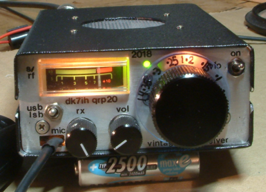
By careful testing and examining I found the reason: The grounding of the rf power amplifier stage was defective due to a connection that had not been soldered properly. After having cured that I found the output was 5 to 6 watts PEP output (very clean). Then, having the project on “GO!”, I finished the design. Thus I got a nice little “vintage style” SSB QRP trsanceiver as a travel or hiking companion:
Basic concept
Frequent readers on my blog know that one thing I really enjoy is building radios based on a minimalist concept. The fewer components you need for a working transceiver, the better it is. At least in my point of view. Here is another one of these “very lean design” transceivers.
The radio originally was designed as a study for my “Old School Transceiver“. After having not built a “real” analog VFO for a number of years I wanted to find out if I still can set up a construction that is really stable concerning frequency. And because it is not very challenging to just watch the result on a frequency counter, a full transceiver had to be built along with the VFO. The VFO was OK, (see later text!) the power transmitter, as mentioned before, was not. Until I had revised it.
The design is another remake of the „Kajman Transceiver“ by SQ7JHM. A design I absolutely love because of its simplicity. The radio basically has been designed for 80 meters (even when lot of websites quote it as a 20m rig) so it shows some weaknesses when adapted to 14MHz without any changes. Thus some improvements had to be made.
Improving performance of the SQ7JHM basic design
Some changes that were top of the agenda to meet my requirements:
The receiver needed a preamplifier for bands where atmospheric noise is not that strong. A dual-gate MOSFET equipped radio frequency preamplifier improves noise figure significantly and can be put into the AGC chain to give more dynamic range and a more pleasant listening experience.
An AGC (automatic gain control) is a good idea if you want to use the receiver in a more comfortable way without the need to lower the volume when strong stations appear. In addition the S-meter reading can be derived from the output of the AGC DC amplifier stage.
A little bit more rf output power can be achieved by using a push-pull amplifier. Linearity also improves to a certain degree when using this design because AB mode combined with separated amplification of the half waves plus suppression of even-order harmonics.
To enhance receiver gain a single stage interfrequency amplifier has been added that is only in use when on receive. It is also connected to the AGC chain.
And, last, a microphone amplifier allows you to talk in a moderate way into the microphone which is good for me because I often have my QSOs when the rest of the family is asleep and not keen on listening to my strange “This is DK7IH/QRP, do you copy?” messages.
The schematic of my enhanced design:
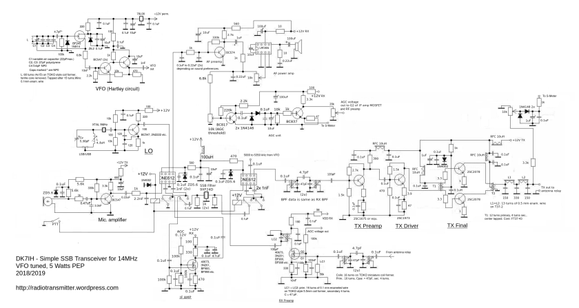
Fascination originates from the fact that you only need a handful of components (OK your hand should not have the size of that of a new born baby!) to set up a working short wave SSB transceiver.
The VFO
SOME THOUGHTS ON FREQUENCY STABILITY
Careful design is the key for stable operation. This means component selection as well as setting it up on the veroboard.
The basic problem for every conventional free running VFO is temperature and its influence on the size of components. Due to the theory of thermodynamics all materials change their mechanical dimensions with temperature. This is caused by the kinetic energy of the molecules forming the crystals of a solid body. Thermal energy leads to enhanced oscillation of the molecules and therefore the need of larger spaces of each in individual molecule in a crystal. Because we have capacitors in a tuned circuit this will affect the values of all caps (wanted and unwanted ones) to a certain degree.
Something that helps the builder is called “temperature coefficient”. This means that electronic components increase OR decrease their respective value when they get warmer. The first is called “positive temperature coefficient”, the opposite is called “negative temperature coefficient”. So, you might guess, the fine art of radio building involves the knowledge of the characteristic behavior of components when heated.
I quote my findings about temperature behavior listed in the article referred to on the beginning of this text:
Capacitors:
Ceramic capacitors: —
Polystyrene capacitor: –
NP0 (C0G) capacitor: no measurable effect
Inductors:
Air coil on polystyrene coil former: +++
Coil wound on T50-6 yellow toroid: +
The more “+” or “-” signs, the more steep the function of T->dC or T->dL is. So you can see: The best choice are polystyrene capacitors combined with coil on a yellow toroid. This combination is likely to outbalance temperature effects. If extra capacity is needed, NP0 caps are recommended.
THE CIRCUIT
From the existing principles of building a free running radio frequency oscillator I prefer the Hartley circuit. It uses a tapped coil (tap about 1/5 from the “lower” end) and saves capacitors compared to the Colpitts design. The tap achieves in-phase feedback. The lower you put the tap to the end the lower the amount of fed back energy will be. This leads to more frequency stability because the circuit does not heat up by excessive internal radio frequency. But be sure that oscillation is always strong enough and does not stop. The Hartley circuit is more simple and caps always inherit the risk of thermal problems when poorly selected.
The tuning is done with a Vernier drive and a homemade variable capacitor. For this a foil variable cap of an old AM radio has been dismantled an reassembled with air as dielectric. Lots of experiments were necessary to get the “frequency swing” correct and the basic capacitance to the right area.
Other measures that support frequency stability are :
Low DC power into the oscillator stage (avoids heating the device up by DC current),
Stabilizing voltage for the VFO stage by 2 consecutive steps,
Using a FET instead of bipolar transistor (no PN boundary layers in a FET),
Very loose coupling between oscillator and buffer stage reduce fed back of impedance changes by the output,
Low impedance output with emitter follower,
Avoid metal sheets (spec. Aluminum) close to the tuning elements! Aluminum sheet metal changes its size largely with even low temperature differences.
PRACTICAL RESULTS
This oscillator is stable. It needs 5 to 10 minutes to settle which is in the normal range of what can be expected. I then can have it tuned to one frequency and there is a maximum change in frequency < 50Hz for hours. And, to compare with synthesizer technology: NO birdies at all. Really not. I love it!
Полностью читайте здесь.